Procedure of Alignment of Shaft of Electrical Machine
Q. Explain the procedure to be followed in aligned two shafts to be
- Directly coupled and
- Indirectly coupled
OR Explain the procedure for levelling and alignment of electrical machine.
 |
| Figure A |
OR Explain procedure of alignment of shaft of electrical machine.
The alignment of direct – coupled drives can be easily made by the following three steps .
- Axial positioning of the shafts.
- Paralleling of shaft axis.
- Centering of the shaft axis.
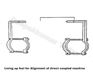
Fix the motor and driven machine on the bed plate in their final position. Level up the motor driven shaft with proper positioning of shims. The spirit level can be used to some extent to check the alignment of the shaft. A lining up tool as shown in the Figure A can be used, which is most useful .
After the shafts have linked properly, the lining up tool is bolted in position as shown in the Figure B. It is so placed that there is a small gap exists between the two points. The two shafts are now rotated together and if the two points do not diverge then the shafts are parallel. When the relative positions of the points remain the same throughout one complete revolution of the shaft, then the alignment of the shaft is correct. It is shown by the following figure.
 |
| Figure B |
The difference in the height of axis of drive shaft and driven shaft can be checked by steel ruler. The straight edge of the ruler is placed on the two outside flanges of coupling as shown in Figure C. If the centre of heights are the same the ruler edge touches each flange along its whole length then they are aligned. When steel ruler touches only one flange, that will mean that one shaft is lower than other. On the other hand, when the couplings are on the same centre, with the shaft not in line with the edge of ruler touches the flange only one or two points.
 |
| Figure C |
To confirm the running true of two coupling halves the gap between two couplings is checked with the help of the filler gauge. The gap is checked by turning the motor shah through 90°, 180°, 270º, and 360° The readings should remain unchanged at all the positions of the shaft. By using the above methods the alignment is checked. The adjustment in driving and driven shaft is carried out packing shims. The foundation bolts are slowly tightened and grouting is carried out, only after careful alignment of two shafts.
Alignments of Indirectly Coupled drives :
The alignment motor for rope and belt drive is carried out before grouting in the slide rails. The motor is firmly bolted to the rails which stand loose on the foundation and is then aligned. A spirit level is placed across the machined surfaces of rails which are then levelled using shims. Only metallic shims are used instead of wooden once. If wooden shims are used, it yields under pressure and swells when moisture enters into wooden shim, while grouting. The rails are levelled in both directions. The motor shaft is then lined up with the driven line shaft and two pulleys, driving and driven are brought into alignment.
For the correct alignment ; the faces of the two pulleys lic in parallel planes. This is achieved when two points on opposite sides of each pulley are connected and a straight line results.
 |
| Figure D |
