Simple Battery Charger
How can I make a 12 volt battery charger at home?
What is battery charger circuit diagram?
How does a battery charger circuit work?
What is battery charging circuit?
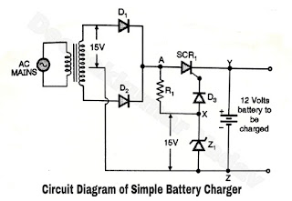
Circuit Diagram of Battery Charger :
- Figure A shows the circuit diagram for a simple battery charger using an SCR.
- The input transformer T is a step down transformer which reduces the 230 V ac mains to 15 Volts. The secondary voltage is rectified by the full wave rectifier circuit.
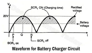
- The zener diode Z1 maintains a constant voltage of 15 Volts, at points “X” as shown in Figure A. The rectified voltage waveform at ‘A’ is as shown in Figure B.
- The dotted line in this figure indicates the battery voltage. When voltage at point A is greater than the battery voltage the SCR1, is forward biased and can conduct if the gate junction is also forward based.
- Thus SCR1 conducts from point P to R as shown in Figure B and charges the 12 Volts battery connected in the circuit.
Operation of Battery Charger :
- As the battery accumulates more and more charge the dotted line goes up and the points P and R will come closer to Q in Figure B, thus reducing the conduction time for SCR1, and hence the charging time of battery.
 |
| Figure A |
- When the battery is fully charged to say about 14 Volts the cathode of SCR1 is at 14 Volts and the gate is at 14.3 Volts.
- This difference of 0.3 Volts between the gate and cathode cannot forward bias the gate junction and hence cannot turn on the SCR1.
- Thus the battery is cut off from the supply and charging will stop automatically.

