Measurement of Partial Discharge
Requirements of Partial Discharge Measuring System
- Most important parameters is apparent charge. The discharge current IC(t) is quantified over small duration of time hence it is called apparent charge. External noise may cause interference with this PD current pulses giving wrong results. So proper filters are necessary.
- The recorded pulses of PD should be above certain limit (which depends on measuring system and noise level).
The Basic PD Test Circuit and PD Currents
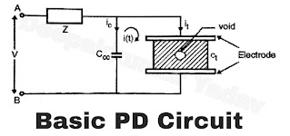
- The basic PD circuits is shown in Figure A.
- The specimen is kept between two electrodes and connected across voltage sources across terminals A and B. A coupling capacitor CCC is introduced. The capacitance of specimen is Ct.
- In the event of discharge, iC, flow through, and at the same time Ct, and it, also flow in the circuit.
- These currents lead the voltage by 90° because these are capacitive currents (Refer Figure B)
- The PD current in will be superimposed an normal power frequency current. Thus small peaks are observed in waveform which can cause large magnification.
- he PD currents are integrated over a period of time that gives measure of apparent charge.
- Straight detection method or high sensitivity circuit method.
 |
| Figure A |
 |
| Figure B |
Straight Detection Method
- The PD current is made to flow through a know impedance known as measuring impedance Zm.
- This creates voltage drop across it. The voltage drop is proportional to current.
- Hence the voltage waveform can be analyzed on CRO to quantity the PD.
- Figure C shows arrangement for this method.
- A band pass amplifier is connected across Zm.
- This amplifier amplifies PD current pulses which can be observed and stored on CRO. Thus analysis is possible.
 |
| Figure C |
- This includes a measuring circuit that is integrated into a test circuit.
- This can be used for detection of repeatedly occurring PD. The external noise is eliminated in this circuit.
- The coupling device can be kept near high voltage supply (V) or away from it. If it is kept away from high voltage supply side its connections to measuring instrument are through optical cable.
- In Figure D, CD is in series with the coupling capacitor Ca and CD is at ground potential.
- In Figure E, CD is in series with the test object Ca.
- The method of measuring PD is same as described earlier.
 |
| Figure D |
 |
| Figure E |
- Even when test circuit is not energised, the switching operations in other circuits, radio frequency interference, HV testing in the vicinity, machine’s commutation and switching ON/OFF of reactive load can cause disturbance.
- When the test circuit is energised disturbance may occur due to partial discharge in neighbouring apparatus c.g. bushings, connecting cables, testing transformer etc. The disturbances do not occur in test object.
- Disturbances may be caused due to presence of harmonics in the system which is indeed due to solid state devices.
- Filtering of noise/screening of unwanted frequency signal is necessary.
- Shielding is a costly affair. The PD detection circuits are very sensitive to disturbances.
 |
| Figure F |
ϕi
= 360 (ti/T)
Where ti is time interval between the preceding positive going transition of test voltage through zero and the PD pulse and T is period of the test voltage.
I
= 1/Tref (lq1l + lq2l + lq3l….lqnl)
Thus it is the sum of absolute values of individual apparent charge q1,q2,…qn during time of reference (Tref). The unit is coulomb/sec.
(iii) Discharge power :
P
= 1/Tref (q1 v1 + q2 V2 +…qn
Vn)
It is the average pulse power fed to the test object due to apparent charge magnitudes q1….qn.
(iv) Quadratic rate :
D
= 1/Tref (q12 + q22 +
…qn2)
It is the sum of the squares of individual apparent charge magnitudes during time interval q1,q2,…qn during time interval Tref.
Calibration of PD Detectors in a Complete Test Circuit
- The measuring instrument is calibrated by injecting a pulse having a charge of known magnitude.
- The charge is injected using a square wave generator. Suppose charge injected is q at a voltage pulse of VT through the capacitor C0.
- ∴ qT = VT C0.
- A small rise time of 60 n sec. is specified for this voltage.
 |
| Figure G |
Digital PD Instruments
- The block diagram of a typical digital PD analyzer is shown in Figure H.
- It consists of a pulse height detection circuit, phase detector circuit, Interface circuit and interface unit of computer.
- The pulse height detection circuit detects the PD pulse, the sampling circuit converts it to digital form. The phase detector detects the zero crossing instant. The polarity of pulse is detected by polarity detector circuit. The interface unit synchronizes the pulse height and phase data required for computer storage. The computer provides effective and user friendly interface.

