Four Quadrant Operation of Dual Converter
Q. Dual Converter
Q. Which converter is suitable for four quadrant operation?
Q. What is meant by four quadrant operation?
Q. How does a dual converter work?
Q. Working Procedure of Dual Converter
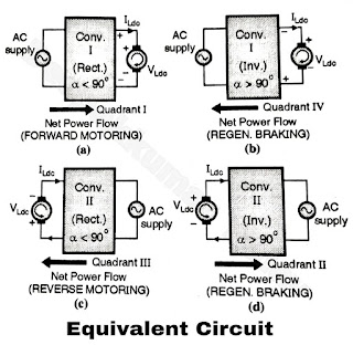
- The first full converter is capable of operating in two quadrants depending on the value of firing angle α. For the values of a less than 90°, this converter works as a rectifier, there by producing a positive average load voltage and load current and operates in the first quadrant.
- Whereas for values of a greater than 90°, it works in the inverting mode, making its average output voltage negative. The load current however remains positive.
- Therefore the first full converter operates in the fourth quadrant allowing the energy to flow from load to source making the regenerative braking possible.
- Similarly the second full converter operates in the third quadrant of the load voltage load current characteristics for a less than 90°.
- The average load voltage and current both are negative. The direction of power flow is from source to load and the dc machine works as a motor.
- The converter operates in the third quadrant. The direction of rotation reverses. This converter acts as an inverter for a greater than 90°. The average load voltage is positive but the average load current continues to be negative, therefore the power flow will take place from load to source.
- The load acts like source i.e. the motor will act as a generator and regenerative braking will take place.
 |
| Figure A |
- The converter thus works in the second quadrant.
- Thus the dual converter works in four quadrants.
- Thus the dual converter is capable of operating in four quadrants as shown in Figure.
- Following table summarizes the results.
|
Parameter |
Converter |
Converter |
||
|
α < 90o |
α > 90o |
α > 90o |
α > 90o |
|
|
1. Mode of Operation |
Rectifier |
Inverter |
Rectifier |
Inverter |
|
2.Average Output Voltage |
Positive |
Negative |
Negative |
Positive |
|
3. Average Output Current |
Positive |
Positive |
Negative |
Negative |
|
4.Flow of power |
Source to load (Forward Motoring) |
Load to Source (Refer Fig. B) |
Source to load (Reverse Motoring) |
Load to Source (Regenerative Braking) |
|
5.Quadrant of Operation |
I |
IV |
III |
II |
|
6.Direction of rotation |
Clockwise (Refer Fig. a) In Figure B |
Clockwise (Refer Fig. b) In Figure B |
Counter clock (Refer Fig. c) In Figure B |
Counter-clockwise (Refer Fig. d) In Figure B |
 |
| Figure B |

In the table Second parameter is average output voltage pls verify that