Ideal Dual Converter
Q. What is ideal dual converter?
Q. What is the essential condition for dual converter?
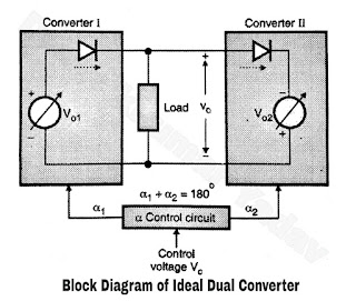
- An ideal dual converter consists of two ideal full converters.
- The ideal full converters are the ones which produce a pure ripple tree dc voltage at the outputs.
Block Diagram of Ideal Dual Converter :
- The block diagram for an ideal converters shown in Figure A. The converters are replaced by a variable dc voltage source in series with diodes that represent unidirectional current flow.
- The magnitudes of the output voltages and vary as the core of the firing angles of the converters.
 |
| Figure A |
- The two converters shown in Figure A can be single phase or three phase full converters. We have just considered their equivalent circuits.
- As shown in Figure A the firing angle control common to both the converters. The fining angles of both the converters (α1 and α2 respectively) controlled by a common control voltage VC.
- The firing angles are adjusted in such a way that the output voltages of both the converters are always exactly equal and of same polarity.
 |
| Figure B |
- Thus both the converters produce the same terminal voltage, one converter operating as a rectifier and the other operating as an inverter.
- The output voltages of the two converter are given by the following equations,
V01 = Vm cos α1
and V02 = Vm
cos α2
In an ideal dual converter
V0 = V01
= -v02
Vm cos α1
= – vm cos α2
cos α1
+ cos α2 = 0
α1 + α2
= 180o
- Thus the control circuit is to be designed in such a way that the sum of the firing angles of the two converters is always 180o, operating one of the converters as rectifier and the other as an inverter. Figure B shows terminal voltage as a function of firing angle for the two converters.
- In this ideal dual converter, the load terminal voltage is the same as the converter voltages and the current has equal freedom to flow through either converters.
|
|
α1 < 90o, |
α1 > 90o, |
|
Converter I |
Rectifier |
Inverter |
|
Converter II |
Inverter |
Rectifier |
- α1 + α2 = 180o therefore, if α1 < 90o then α2 must be greater than 90o and vice versa. These results are tabulated in above table.
