Power Frequency Test of Isolators
- Power Frequency Voltage Withstand Test
- Rated Short Time Current Test and momentary Current Withstand Test
- Dielectric Test or Over Voltage Test
Power Frequency Voltage Withstand Test
- This test is similar to dry withstand test explained for insulators.
- The test is performed in wet and dry conditions separately. Before commencement of the test, the insulator is exposed to artificial rain produced as per IS 2071 (Part 1)–1974 for at least one minute before application of voltage and there after throughout the test.
- The setup in exactly similar to dry and wet flashover test.
- The test voltage applied to the insulator is the specified value of the wet power frequency withstand voltage adjusted for atmospheric condition at the time of test.
- The voltage of about 75% of the test voltage is applied and then increased gradually to reach the test voltage in a time not less than five seconds.
- The test voltage is maintained at this value for one minute as per L.S. 2071 (Part II)–1974.
- Two flashover at positive polarity and one flashover at negative polarity is permitted.
Rated Short Time Current Test and momentary Current Withstand Test
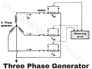
- This test is carried out with 3 phase supply. A 3 phase generator supplies required short circuit current.
- The isolators are closed and are connected to 3 phase generator as shown in Figure.
- The star point is earthed. Shunts are included in the circuit for measurement of current.
- A short circuit current of about 25 times rated current is passed for one second.
- One phase has peak current of 2.5 times rated mms short circuit current during first cycle.
- The current is known as momentary short circuit current.
- There is heating of isolators contacts, different joints, etc.
- The heating effect should be within permissible limits.
Dielectric Test or Over Voltage Test
- This test is similar to dielectric test or over voltage test on circuit breaker.
- This test is performed on both internal and external insulation of circuit breaker.
- It performed for two conditions.
- Circuit breaker closed
- Circuit breaker open
Circuit breaker closed
The tested part is R phase i.e. voltage is applied to R phase pole of circuit breaker and Y phase, B phase and metallic frame structure of circuit breaker is earthed. Same procedure is repeated with Y phase and B phase.
Circuit breaker open
The test voltage is applied to circuit breaker contacts i.e. R, Y, B poles of circuit breaker are connected to bus bar side and voltage is applied from other side consecutively on each phase. The reference range of standard voltage to be applied for this test are as below.

