Special Tests of 3 Phase Induction Motor
Q. Explain the special tests of 3 phase induction motor.
Open Circuit Voltage Ratio Test :
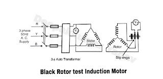
The test is carried out to find out the voltage ratio or turns ratio. As shown in figure A the rotor resister starter is disconnected from the springs and voltmeter is connected across sliprings. Rated voltage is given to stator windings through auto transformer, its value is T1.
 |
| Figure A |
The voltage across sliprings = T2 and it is the line voltage which should be divided by i.e. to get. Thus the readings of are taken across different sliprings and in different positions of rotor. And average of these values is taken. The voltage ratio should be equal to turns ratio but it is not so because of leakage of stator flux. To obtain the true ratio, the arrangement is made as shown in figure B. And above procedure is repeated from rotor side. i.e. is applied to motor through auto transformer and is measured.
The turns ratio = Primary turns or stator turns ‘ ‘ per phase / Secondary turns or rotor turns ‘ ‘ per phase
= + / +
= + /
 |
| Figure B |
Locked rotor reading of voltage, current and power input at suitable reduced voltage :
This test is also called ‘Blocked rotor test’ or ‘Short circuit test’. In this test the rotor is not allowed to rotate. The rotor can e held by hand in case of small motors.
for big motors following arrangements are used.
- Dynamometer
- Rope and pully
- beam clamped rigidly to the motor shaft. ( With these arrangements the torque can also be measured.)
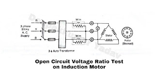
Low voltage is applied across the stator terminals through a three phase autotransformer. The respective meters are connected in the circuit as shown in figure C. The violtage is gradually increased to a value so that full load current flows through the windings. The test is similar to short circuit test of transformer.
 |
| Figure C |
The voltage required to circulate rated current is low. The power input to the stator is wasted as R loss in stator and rotor windings. The coreloss is negligibly small. The sum of two wattmeter readings give total input power (i.e. + ). The average of three ammeter readings give short circuit current ( ) and volt meter give short circuiting voltage ( ). It should be noted that the testing of induction motor under locked condition with polyphase power involves unusual mechanical stresses and high rates of heating, therefore it is necessary that :
- The mechanical limbs of locking the rotor should be of adequate strenght to prevent possible injury to personnel or damage to the equipment.
- The direction of rotation be established pripor to the test.
- The winding get heated up so the test should be carried out as rapidly as possible.
